This article explains how to cut curved, sloped, and free-form stone designs using a 5-axis bridge saw, focusing on practical shop workflow: defining manufacturable geometry, building stable CAD/CAM toolpaths (lead-in/lead-out, tilt control), supporting the slab to prevent edge damage, keeping wet cutting consistent, and using early inspection checkpoints so multi-piece sets install cleanly without manual “rescue work.”

+86 134 8948 6615

Quick Summary
Cutting curved, sloped, and free-form stone designs with a 5-axis bridge saw is a workflow problem before it’s a machine problem. The winning approach combines clean input geometry (templating/scan), CAM toolpaths that control lead-in/lead-out and tilt angles, multi-pass strategies to protect edges, stable slab support, and simple inspection checkpoints that prevent “looks fine until installation” surprises. This guide walks through the exact production logic stone shops use to turn complex shapes into repeatable parts—without relying on heavy manual correction.
Why these shapes fail in real production
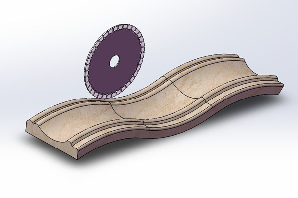
Curved edges, sloped surfaces, and free-form outlines don’t usually fail because the saw “can’t cut the line.” They fail because the geometry forces bad cutting conditions: unstable exit points, changing contact angles, weak corners, and multiple re-clamps that gradually drift the part away from the original datum.
A 5-axis bridge saw changes the game because it can control orientation as well as position. But here’s the part most buyers miss: the machine only performs as well as the workflow feeding it. If the CAD file is messy, the toolpath is rushed, or the slab isn’t supported correctly, you’ll still get chips, mismatched seams, and on-site fitting headaches.
In QZGEE project reviews, the best results come from treating irregular cutting like a repeatable system: input geometry, toolpath strategy, wet cutting control, and inspection checkpoints that catch problems early.
Step 1: capture the real shape correctly (templating or scanning)
If the project is a replacement piece or must match existing conditions, use templating or scanning. Curves that exist in the field are rarely “perfect arcs,” even if the drawings say they are.
When to template
Template when the job is small, the curvature is simple, and you can physically capture the outline accurately.
When to scan
Scan when the curve is long, the slope interacts with multiple surfaces, or the installation environment is imperfect (renovations, older buildings, uneven walls, non-square corners). Scanning reduces the risk that the shop cuts a perfect part for an imperfect site.
 |
 |
Step 2: clean CAD before CAM
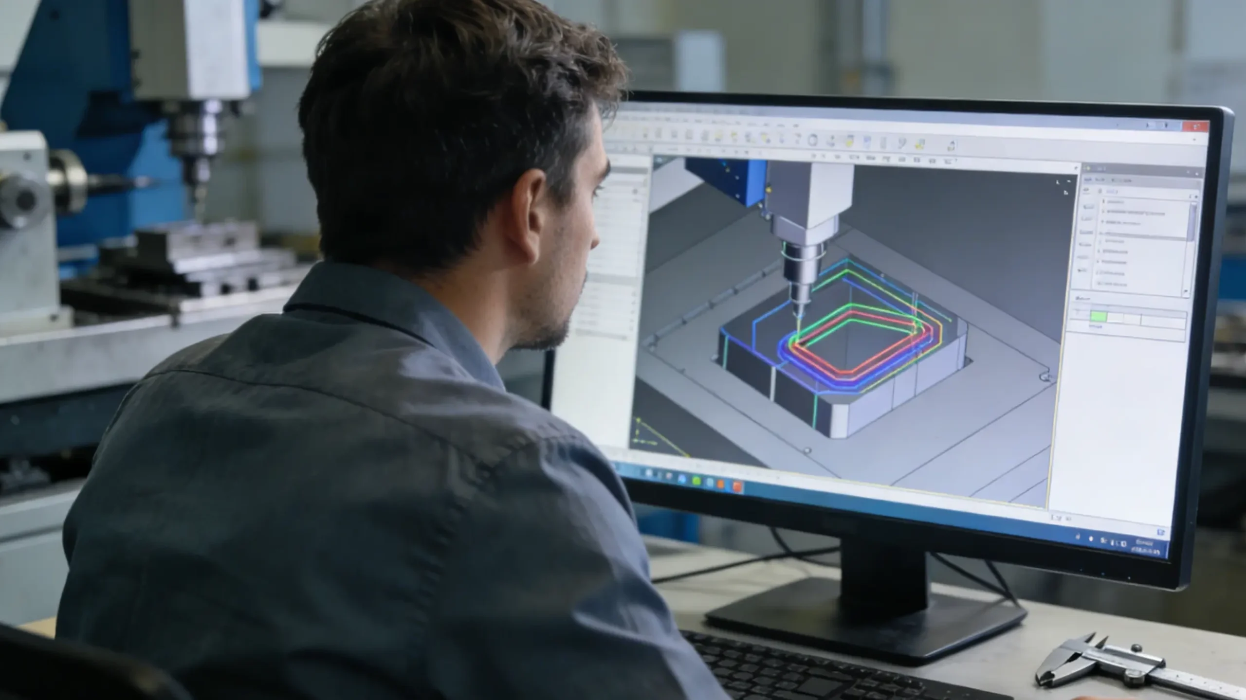
CAM does not fix bad geometry; it amplifies it. Before toolpath programming, clean these problems.
Remove micro-segments and duplicate curves
Tiny segments cause direction changes that show up as waviness after polishing, especially on reflective finishes.
Confirm tangent continuity at curve joins
Curve-to-line or spline joins that are not tangent-continuous are a common reason for “flat spots” and seam shadows under lighting.
Make slope intent explicit
Define the slope angle, reference plane, and where the slope begins and ends. If the slope transitions into another surface, define that transition curve, not just the endpoints.
Step 3: select a cutting strategy that matches the stone and the shape
Curves and free-form edges are edge-quality jobs. That means your strategy should prioritize controlled force and clean exits rather than maximum speed.
Use multi-pass logic where it matters
For tight radii, thin lips, and fragile corners, plan a rough pass and a finish pass. The finish pass is where you protect the edge and improve the polish-ready surface.
Plan entry and exit like a seam designer
Lead-in and lead-out are not “CAM details.” They determine whether the edge survives. Avoid exiting directly at a visible corner whenever possible. If you must exit at a corner, soften the conditions: lighter pass, adjusted approach direction, and stable coolant.
Use tilt deliberately, not constantly
On a 5-axis bridge saw, tilt is powerful but should be controlled. Excessive tilt changes contact behavior and can introduce new marks. Use tilt where it improves seam intent: bevel consistency, compound miters, and certain sloped transitions.
Step 4: build the job in CAM with a “curve-first” mindset
Curves are unforgiving because humans see curve defects instantly. Build your CAM operations so the curve gets the best conditions.
Typical operation order for curved/free-form parts
Most shops get cleaner results with an order like this:
-
establish datum and reference cuts
-
rough cut the outline leaving a small allowance
-
perform bevel/miter operations while the part is stable
-
finish cut the outline to final
-
optional cleanup pass on critical visual edges
The reason is stability: you want the part supported and located well during the operations that affect seams and visible lines.
A practical CAM planning table
Use this as a repeatable planning checklist when your shop is quoting or programming free-form work.
| Geometry type | Common risk | Best practice in CAM | What to inspect |
|---|---|---|---|
| Curved outline edge | corner chipping and waviness | rough + finish outline, stable lead-out, curve smoothing | radius consistency, edge breakout at exits |
| Sloped surface edge | seam shadow and angle drift | explicit slope plane, controlled bevel tilt, consistent tool angle | slope angle consistency, seam line fit |
| Free-form multi-piece set | mismatch across pieces | shared datum, identical toolpath logic, batch sequencing | joint gap stability across pieces |
| Tight internal cutouts | micro-chipping in corners | smaller radius strategy, multi-pass, careful exit direction | corner integrity, cutout dimensional fit |
Step 5: Support the Slab Like You Actually Want the Edge to Survive
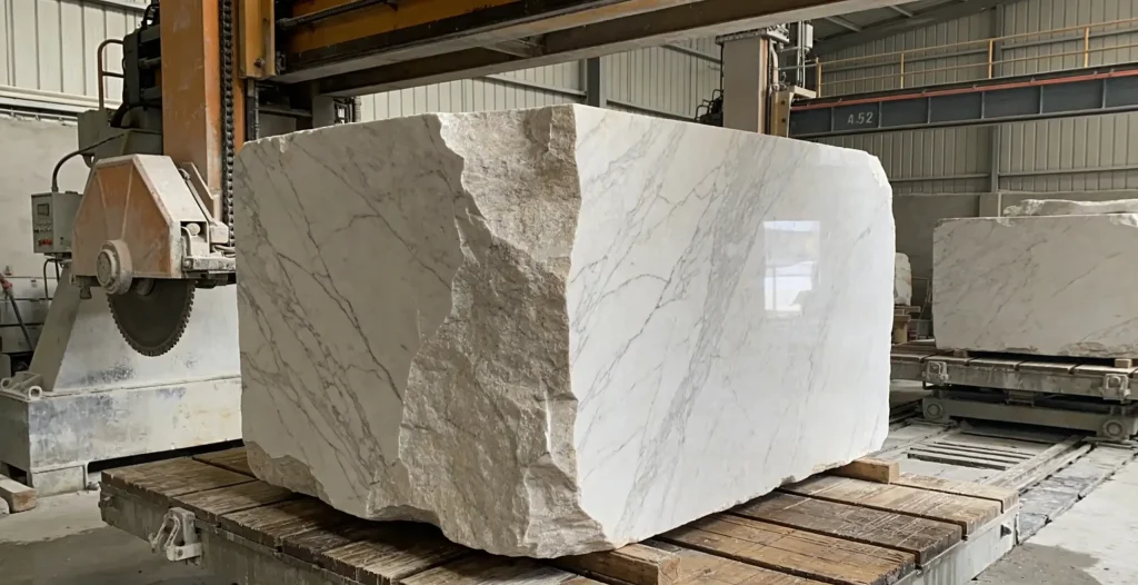
Poor support creates vibration and micro-fractures that often don’t show immediately. They appear later as edge bruising, unexpected chips during polishing, or seam mismatch at installation. For curved and free-form work, support near the cut path matters more than “overall support,” because the tool force concentrates along the curve and the exit zone.
Avoid Floating Zones Near Curves
If a curved area is left unsupported, the slab can flex slightly under cutting load. That flex is enough to damage the edge microstructure and create bruising that becomes visible after finishing. The fix is not “more supports everywhere,” but targeted supports where the tool will travel, especially near exits and thin lips.
Use Sacrificial Support Where Needed
A sacrificial layer or backer strategy reduces exit breakout and protects fragile edges, particularly on thinner parts or engineered materials that tend to chip at the last millimeters of the cut. The goal is to keep the edge supported until the cut is fully complete, so the tool exits into stability rather than into free space.
Keep Wet Cutting Consistent
Curved cuts often change nozzle distance and spray angle as the head moves, which can make coolant delivery uneven. Uneven coolant usually means uneven tool behavior, and that shows up as inconsistent edge quality along the curve. The target is stable cooling and reliable slurry evacuation, not dramatic spray.
Cutting Curved Stone Edges With a 5-Axis Bridge Saw
Curved edges are where “looks fine on the machine” can still fail later. The three performance targets are curve smoothness, edge integrity, and radius repeatability. If any one of these drifts, the problem usually appears at finishing or during dry fit.
Curve Smoothness Comes From Geometry and Motion, Not Polishing
Polishing can hide minor tool marks, but it will not fix a wavy curve. A clean curve starts with clean CAD and a toolpath that avoids unnecessary direction changes. When the toolpath is stable, the finishing workload becomes predictable and the curve reads correctly under lighting.
Edge Integrity Depends on Exits
Curves often have multiple exit points, especially where a curve meets a straight section or a corner. Those exits are the most common locations for micro-chipping. A practical approach is to place exits away from highly visible zones when possible, and reduce cutting aggression at exits so the final edge remains intact.
Repeatability Comes From Using One Strategy Across the Batch
If the project has multiple curved panels, do not “improve the CAM” halfway through production. Lock the strategy first, then adjust only if inspection data proves it’s needed. Curve projects fail when each piece is cut with a slightly different logic.
Cutting Sloped Stone Details and Compound Transitions
Slopes reveal defects under light. Even a small angle drift can create a seam line that reads as a shadow. That’s why sloped details require both a consistent reference and a consistent machining intent.
Define a Slope Reference and Keep It Consistent
A slope without a reference is just an opinion. In production, the reference must be a plane and a consistent datum point. Once the reference is defined, every part in the set can be machined and checked against the same intent.
Use Tilt to Preserve Seam Intent
Tilt is valuable on slopes when the joint must close consistently. The purpose is consistent joint behavior along the slope, not maximal axis movement. Controlled tilt supports seam stability and reduces the chance of mismatch lines appearing after assembly.
Inspect Slope Angles at Multiple Points
A slope can be correct at one end and drift at the other. Check slope angles at points that correspond to seam lines or installation references, because that’s where small drift becomes a visible problem.
 |
 |
Cutting Free-Form Stone Designs Without Turning It Into Handwork
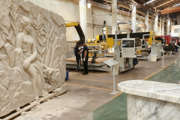
Free-form edges are the most common reason shops fall back to manual correction. The solution is to define what matters most visually and structurally, then build the cutting plan to protect those features so finishing becomes a controlled step, not a rescue.
Build a Datum Strategy That Matches Installation Reality
If installers locate the piece from one edge and one corner, the datum should reflect that. If the piece is located by hardware holes or bracket interfaces, the datum should be built around those interfaces. A free-form part can be perfectly cut and still fail if it’s referenced differently in the shop and on site.
Protect Critical-to-Look Edges With a Finishing Pass
Edges that will be touched, seen, and lit should never be treated like rough cuts. A finishing pass stabilizes edge quality and reduces polishing effort, especially on curves and visible transitions where small defects become obvious.
Use Inspection Checkpoints Early
Do not wait until the piece is fully finished to discover seam drift. Check joint-critical dimensions and bevel behavior early, when correction is still possible without redoing the entire part.
Common mistakes that cause “beautiful sample, painful batch”
These are the most repeatable reasons free-form jobs go wrong.
Mistake 1: cutting to final in one pass
It saves time on the machine and costs time everywhere else. A one-pass final cut often increases chipping and makes finishing unpredictable.
Mistake 2: ignoring lead-out behavior
Exit behavior is where chips are born. Lead-out planning is one of the simplest “CAM upgrades” that reduces manual repair.
Mistake 3: letting the slab support decide the quality
If support is inconsistent, results are inconsistent. Support is part of the cutting process, not a setup detail.
Mistake 4: no shared datum across multi-piece sets
Free-form sets fail when each piece has a slightly different reference. Shared datum design keeps the set consistent.
Buyer checklist: what to specify when sourcing free-form cutting
If you’re buying irregular cutting as a service, or qualifying a supplier, specify the workflow—not just the machine.
- Ask for toolpath proof for one representative curve
You don’t need the entire program. You need evidence they manage lead-in/lead-out, curve smoothing, and bevel intent. - Ask how they control re-clamping
If the supplier needs multiple re-clamps, ask how they preserve datum and ensure the set matches. - Ask what they inspect before finishing
The best suppliers measure joint-critical features early and avoid finishing a part that will fail at assembly.
This is also where QZGEE typically recommends buyers align the drawing tolerances with “critical-to-look” and “critical-to-fit” features, so the machining plan matches the real project risks.
Conclusion
A 5-axis bridge saw can cut curved, sloped, and free-form stone designs cleanly, but only when the workflow is built for irregular geometry. Clean input geometry, controlled CAM strategies, multi-pass edge protection, stable slab support, consistent wet cutting, and early inspection checkpoints are the difference between scalable production and manual rescue work.
If your project demand includes curved panels, compound miters, sloped seam intent, or free-form multi-piece sets, the smartest move is to qualify suppliers by their process discipline, not just their portfolio photos. This is the production mindset QZGEE builds around: turning complex geometry into repeatable output that installs cleanly the first time.
FAQ
1.Can a 5-axis bridge saw cut true 3D bowls and deep sculpted pockets?
A 5-axis bridge saw can handle many cutouts, bevels, and certain shaped features, but deep 3D bowls and complex pocketing are usually more efficient on a stone machining center. If the job includes heavy 3D machining, consider a hybrid workflow or confirm the supplier’s specific tooling and CAM capability.
2.What’s the best way to avoid chipping on curved edges?
Use a rough + finish strategy on critical edges, manage lead-out away from visible corners, keep coolant consistent, and avoid aggressive final passes near exits. Chipping is often an exit and force-control problem rather than a “tool quality” problem alone.
3.How do I ensure multiple free-form pieces match during installation?
Use shared datum references across the full set, keep toolpath logic consistent across pieces, and inspect joint-critical edges before finishing. Matching is a workflow discipline, not a final polishing step.
4.What file format is best for curved and free-form outlines?
DXF/DWG can work for 2D outlines, but STEP/IGES or solid models are often better when slopes and compound transitions are involved. The key is clean geometry with continuity, not just the file type.
5.Do sloped joints require 5-axis?
Not always, but 5-axis makes sloped seam intent more controllable, especially when the slope interacts with a curve or compound miter. The value is bevel consistency and reduced re-clamping.
References
-
OSHA — Respirable Crystalline Silica Standard (29 CFR 1926.1153), U.S. Department of Labor.
-
NIOSH (CDC) — Silica Hazard Controls in Stone/Construction Work: Wet Methods and Exposure Reduction Guidance.
-
Natural Stone Institute — Fabrication and Shop Safety Best Practices (wet cutting, handling, QC workflow).
-
ISO GPS System — Geometrical Product Specifications (tolerance definition concepts for manufactured parts).
-
Siemens Digital Industries Software — CAM simulation and collision avoidance workflow notes.
-
Autodesk Fusion / PowerMill CAM Guides — 5-axis toolpath strategies, lead-in/lead-out, smoothing concepts.
-
SME (Society of Manufacturing Engineers) — 5-Axis Machining fundamentals: accuracy, process planning, verification.
-
Sandvik Coromant Technical Guide — Surface finish drivers (scallop height concept), tool engagement, and strategy selection.
Previous News
Why Stone Fabricators Are Switching to 5-Axis C...Next News
What Is a 5 Axis CNC Bridge Saw? (Complete Guid...Feature Product
-
 Durable Custom Backpack – Stylish, Functional, ...
✅ Key Features Premium Material: High-quality...